
As per CAPP – Canadian Association of Petroleum Producers, a flare system is defined as the controlled burning of natural gas that cannot be processed for sale or use because of technical or economic reasons.
On the Other hand, API 537 defines a flare system as the system provided in a refinery or petrochemical plant to ensure the safe and efficient disposal of relieved gases or liquids.
The efficient flaring system exists at any facility accommodating Hydrocarbon pressurized systems such as:
Flares are primarily used for burning off flammable gas released by pressure relief valves during any over-pressure scenario of plant process unit/equipment, due to process upset or during startups & shutdowns, and for the planned combustion of gases over relatively short periods.
Flare systems are used for a variety of activities such as:
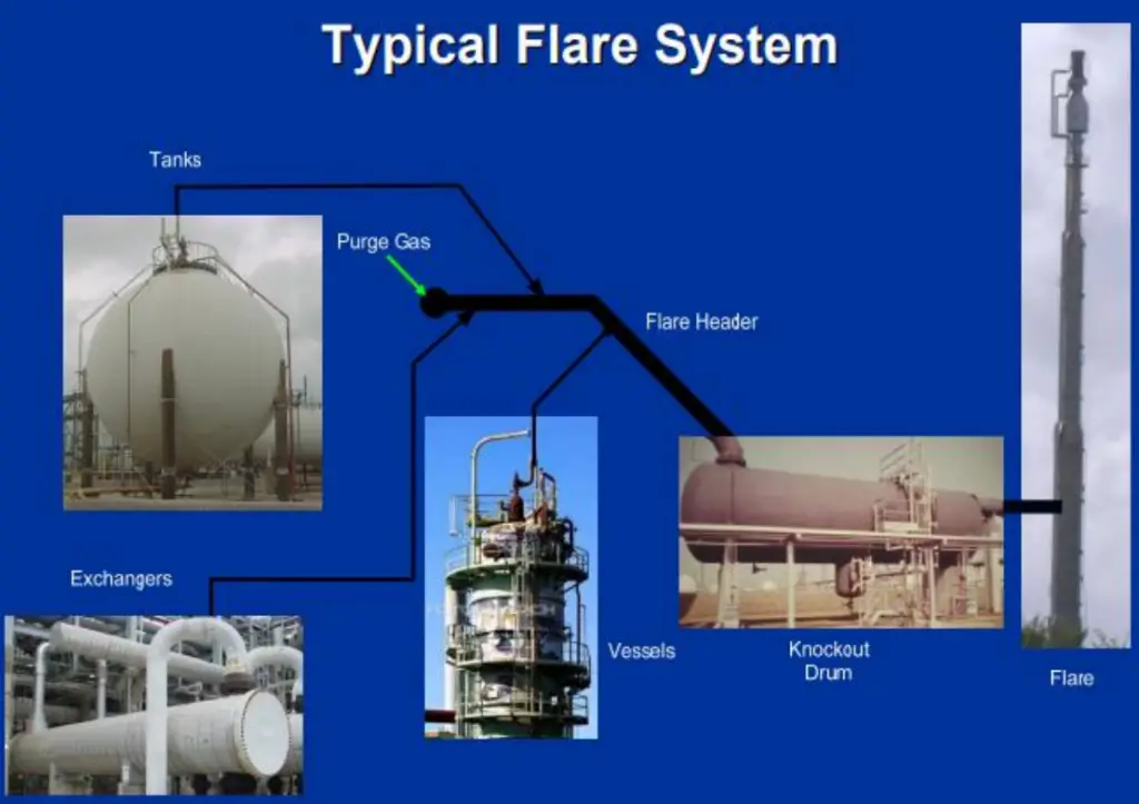
Fig. 1 shows a typical flare system in a process plant. The important features of a flare system are
The flaring system is normally activated during the following situations
There is in fact no standard composition and it is, therefore, necessary to define some group of gas flaring according to the actual parameters of the gas.
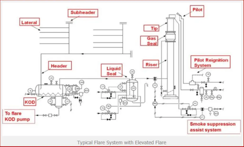
Fig. 2 below shows a typical flare system with elevated flare. The important flare system components are marked in the image.
All the above flare types can be either single-point or Multi-burner staged flares. Also, Flares can be classified as either
The Flare system is normally selected based on the following considerations.
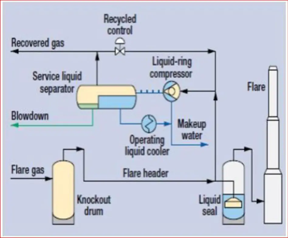
There are many types of FGRS (Flare Gas Recovery Systems) in the industry:
The gas collection and compression into pipelines for processing and sale is a well-established and proven approach to mitigating flaring and venting. According to environmental and economic considerations, FGRS has increased to reduce noise and thermal radiation, operating and maintenance costs, air pollution, and gas emission, and reduces fuel gas and steam consumption. Fig. 3 below shows a typical example of a flare gas recovery system.
API 537 is used for flare system design. This standard is applicable to Flares used in pressure-relieving and vapor-depressurizing systems used in General Refinery and Petrochemical Services. Although this standard is primarily intended for new flares and facilities, it may be used as a guideline in the evaluation of existing facilities together with appropriate cost and risk assessment considerations. API 537 must be referred to in consideration with
The plant owner or the plant designer must provide these factors to define the flaring requirements.
The prime objective of a flare system design is safe, effective disposal of gases without compromising appropriate design considerations like:
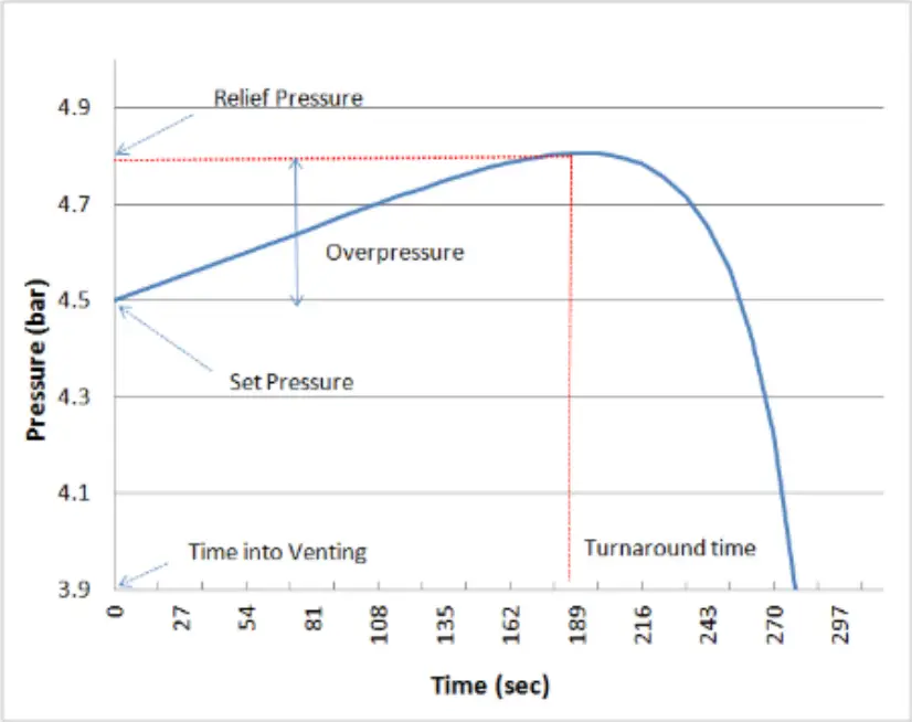
The take-off point for flare header sizing is to have a proper relief load calculation based on the worst credible scenario, where the pressure will increase until a predetermined relief pressure is reached, at which point the relief pressure valve will open, decreasing the pressure after the turnaround time. Refer to Fig. 4.
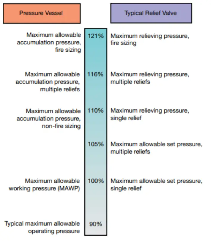
The ASME Boiler and Pressure Vessel Code Sec VIII sets out requirements for standard pressure vessels (left) and the relief valves (right) protecting them as a percentage of the maximum allowable working pressure (MAWP) as shown in Fig. 5.
Refer to Fig. 6 below which shows a typical flowchart explaining the steps for the relief valve sizing procedure.
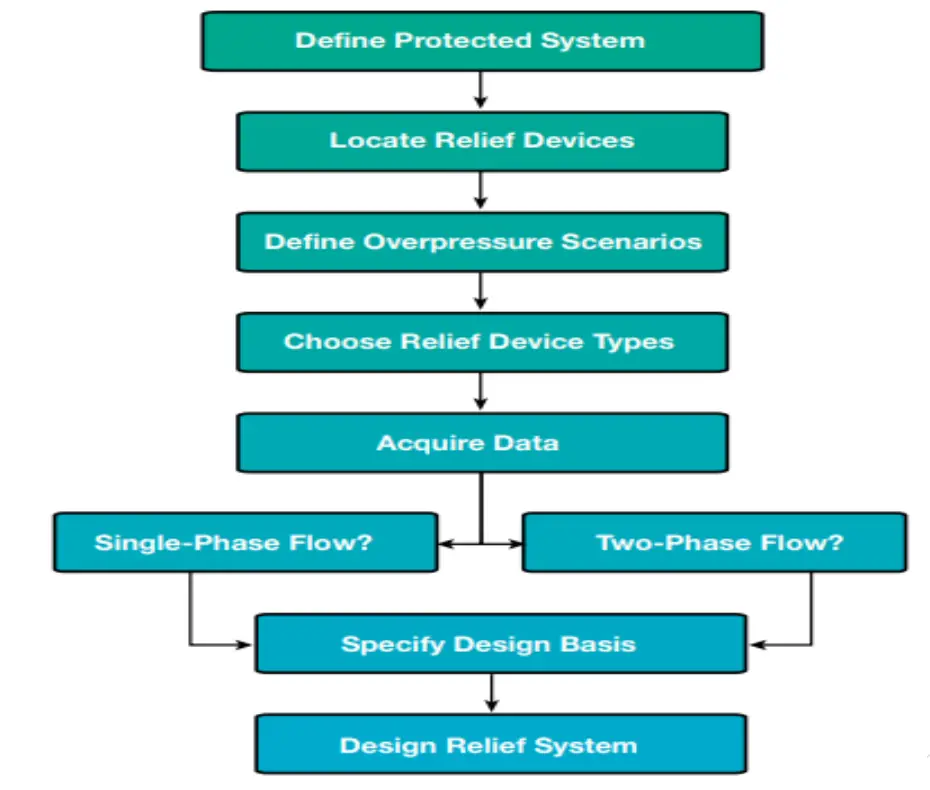
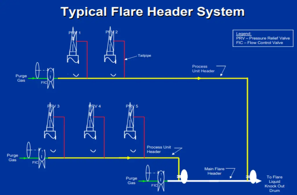
Fig. 7 below shows a typical flare header system for a processing plant.
Steps for finding ‘the maximum’ relief load for a specific process plant:
The sum of all pressure losses starting from the flare stack up to the safety valve yields the total backpressure. This backpressure must be lower than the maximum backpressure allowed in the system & corresponding to the lowest set pressure of the safety valves.
The flare header is sized to limit the backpressure of each pressure relief device during various emergency events. The hydraulic design is a line sizing/rating problem:
The objectives of a knock-out drum are
Fig. 9 shows a typical known out drum (KOD). KOD is sized based on API 521.
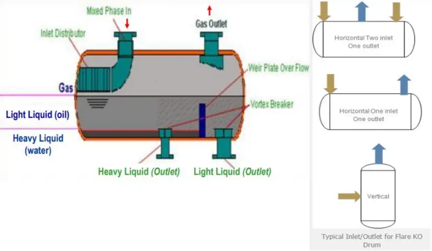
Long-term field experience has shown that the dropout velocity in the
drum may be based on the necessity to separate droplets from 300 μm to 600 μm in diameter.
Flare Load, Radiation, and stack height:
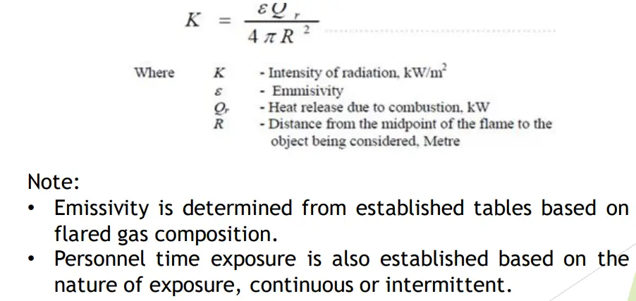
Flare stack height depends on the flame radiation intensity, therefore you will need first to estimate the generated radiation in order to be able to identify the minimum acceptable stack height. Thermal radiation can be calculated by the following equation (Fig. 11):
Flame length is a determining factor for the intensity of radiation and its angle in relation to the stack. It can be calculated using the following equation (Fig. 12):
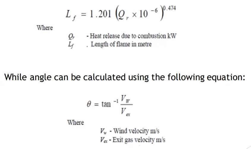
Using Flame length and flame angle, Radiation intensity can be determined and accordingly flare stack from charts.
READ Bracing Connections/Cross-bracing Design ExampleLiquid Seal Drum prevents the flashback from flare tip back to flare headers. It also helps to avoid air ingress into the flare system when the flare system is integrated with a flare recovery system or due to hot gas thermal contraction and/or condensation which can result in a substantial vacuum in the flare header. Fig. 13 shows a typical liquid seal drum.
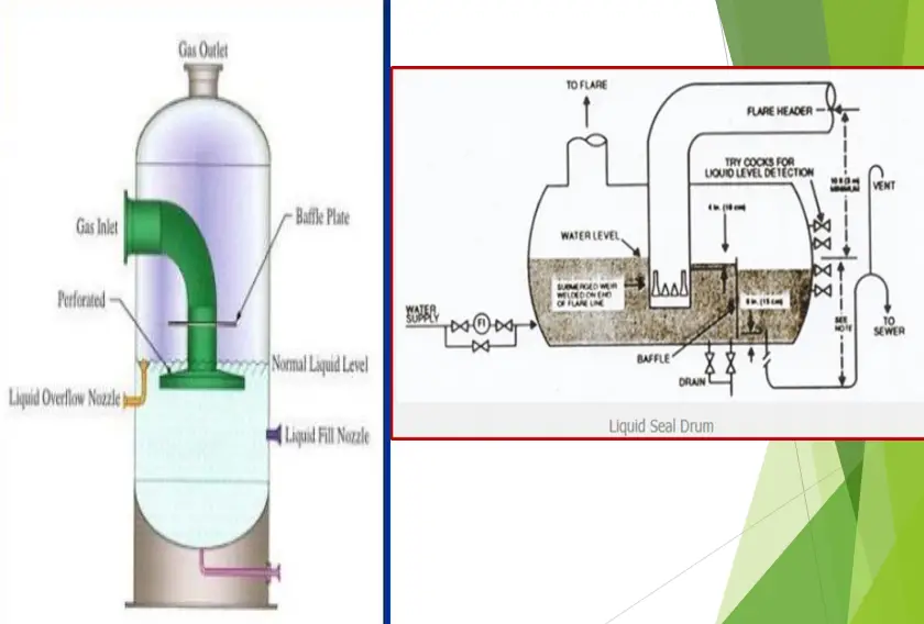
Note that the maximum vacuum protection achievable may be limited by piping and vessel elevations, In addition to maintaining the proper liquid level and restoring the level promptly after any hot relief and before the vacuum forms.
For extremely cold releases, the water as a liquid sealing fluid is not recommended. In such cases, water-glycol mixtures of sufficient concentration shall be used.
As we get familiar with the impact of improper flaring on health and the environment, also it is highly required to measure the HC quantities sent to flare to decide on the plant performance, identify gaps and define the mitigating actions to eliminate or at least reduce flaring.
When trying to measure gas flaring, There are many challenges, including diameters of large pipes, high flow velocities over wide measuring ranges, gas composition changing, low pressure, dirt, wax, and condensate.
Important criteria to be considered to decide on the flow measurement instruments:
The main types of flow meter technologies for flare gas measurement in the industry are listed in Fig. 14 below: